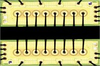
Hybrid Circuits - LTCC & Thick film
Bare die have been used to build hybrid circuits since the 1970s and originally were built exclusively for the military market. The hybrid circuit was effectively the first board/system miniaturization technology available in the market. However, whilst highly reliable, it was also expensive so became economically unsuitable for some markets and usages as the electronics industry evolved.
The introduction of SMT (Surface Mount Technology) assembly and shrinkage of plastic components at modular and single level created a solution for commercial users where high reliability was less critical but size reduction and cost down could be achieved. In parallel, bare die became integrated in plastic MCM (Multi-Chip-Modules), SiP (System-In-Package) and Flip-Chip direct to board in response to these drivers.
Hybrid circuits using bare die are still in use today and where high reliability and temperature resilience are required they still represent the most effective way to miniaturize a system on a single substrate.
Key benefits:
- Temperature & Reliability
- Form factor
- Performance
- IP protection
Temperature & Mechanical Reliability
The main advantage of using bare die in hybrid circuits is the temperature range capability, mechanical reliability combined with achievable size reduction of the system.
The most common substrate processes are LTCC - Low Temperature Co-fired Ceramic and Thickfilm
Similar to ceramic MCM or single-chip ceramic package bare die on hybrid circuits can be exposed to extreme temperature ranges of -40°C to 125°C for Automotive, -55°C to +125°C for military, and -55°C to +>175°C for some oil & gas platforms without the assembly deteriorating and causing reliability issues.
This places emphasis on the bare die performance itself, which can be allowed to operate much closer to it's maximum working junction temperature and also operational behavior at lower temperatures can be tested. In the case of the hybrid circuit an important benefit is that the entire system can be characterised as a unit for reliability at temperature extremes.
Form Factor
Hybrid circuits are planar in layout and follow different design rules compared with standard PCB.
Similar to PCBs hybrid circuits can be multi-layer so with clever design the form factor can be reduced while maintaining reliability. A key benefit of the hybrid circuit is also that passives can be integrated into the substrate to save additional space or increase integration.
Similar to SiP where specialist integration is required, a hybrid can be considered an alternative to ASIC when all functional aspects can't exist on single chip and the application profile needs reliability. However the production costs must also match the application commercial profile.
Performance
The main benefit of using die in hybrid circuits is temperature performance and mechanical ruggedness under shock and vibration.
Depending on choice of substrate material it's possible to develop a circuit that can operate well above 200°C where required.
Hybrid circuit substrates also offer better thermal conductivity than PCB and also exhibit higher breakdown voltage capability.
Substrate integrated passives increase reliability by reducing interconnect points. Integrated passives also allow the circuit to be precision tuned to produce highly repeatable and stable characteristics.
IP Protection
Hybrid circuits due to their specialised design and production flow are very hard to copy. Additionally by using bare die the BOM (Bill-Of-Material) used is also not easy to gather.
Hybrids Versus Individual components
Hybrid pros:
- Reliable under extreme environmental temperature
- Suitable for high voltage applications where normal PCB can't support
- Highly stable electrical performance and low deviation per unit
- Smaller X-Y profile than individual ceramic components or MCMs
- Can integrate both bare die and standard packaged components where needed
- Very difficult to reverse engineer
Hybrid cons:
- Expensive unless the application benefits pay-back
- Requires specialised design-flow and process
- Sensitive to die revision or piece part change
- Difficult to dual source or move production location
- Reliant on consistency and availability of bare die supply.
Indvidual ceramic components pros:
- Ease of availability
- Pre-qualified, characterised temperature performances
- Substrate footprint not effected by die geometry changes.
Individual ceramic components cons:
- Largest X-Y footprint
- Each individual component must be qualified in the system
- Lower performance potential in combination with other components.
Hybrid Circuit benefits in summary
Using bare die in hybrid circuits remains a specialized method of reducing form factor while offering very high reliability. Hybrids are a complex and bespoke solution which can provide an attractive solution for the right application. Despite the age of the technology, hybrid circuit use is on the increase in markets like automotive, industrial, military and medical. The challenge for the hybrid circuit is to continue being able to adopt and assemble using the latest technology and interconnect methods for bare die.